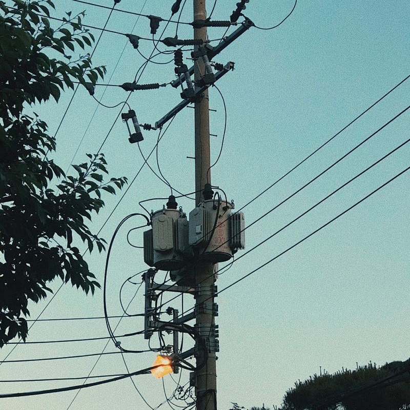
Complete knowledge of transformer main protection and backup protection
1. Common faults and anomalies of transformers
Transformer faults can be divided into internal faults and external faults.
Internal fault refers to the fault that occurs inside the case, such as interphase winding short-circuit fault, one-phase winding inter-turn short-circuit fault, short-circuit fault between winding and iron core, winding line break fault, etc.
External faults refer to various inter-phase short-circuit faults between the external lead lines of the transformer and single-phase ground faults caused by flashover of the insulation bushing of the lead lines through the box shell.
Transformer failure is very dangerous. Especially when the internal fault occurs, the high-temperature arc generated by the short-circuit current will not only burn the insulation and iron core of the transformer winding, but also cause the transformer oil to decompose by heat and produce a large amount of gas, causing the transformer shell deformation or even explosion. Therefore, when the transformer fails, it must be cut out.
The abnormal situation of the transformer mainly includes overload, oil level reduction, overcurrent caused by external short circuit, high oil temperature of the transformer in operation, high winding temperature, high transformer pressure, and cooling system failure. When the transformer is in abnormal operation state, an alarm signal should be given.
2. Configuration of transformer protection
The main protection of short circuit fault: mainly includes longitudinal difference protection, heavy gas protection and so on.
Short-circuit fault backup protection: mainly compound voltage lock overcurrent protection, zero sequence (direction) overcurrent protection, low impedance protection and so on.
Abnormal operation protection: mainly overload protection, over-excitation protection, light gas protection, neutral gap protection, temperature oil level and cooling system fault protection.
3, non-electric protection
The transformer protection composed of non-electric gas such as oil, gas and temperature is called non-electric protection. Main gas protection, pressure protection, temperature protection, oil level protection and cooler full stop protection. Non-electric protection according to the field needs to act in tripping or sending messages.
(1) Gas protection
When the transformer internal fault occurs, due to the short-circuit current and short-circuit arc, the transformer internal will produce a lot of gas, while the transformer oil flow speed up, the use of gas and oil flow to achieve protection called gas protection.
Light gas protection: When there is a slight fault or abnormal inside the transformer, the fault point is overheating, causing part of the oil to expand, the gas in the oil to form bubbles into the gas relay, the light gas protection action, and the light gas signal.
Heavy gas protection: When a serious fault occurs in the transformer tank, the fault current is large, the arc causes a large amount of transformer oil to decompose, resulting in a large amount of gas and oil flow, the impact plate makes the heavy gas protection action, sends out the heavy gas signal and the exit trip, and cuts the transformer.
Heavy gas protection is the main protection for internal faults of the tank, and it can reflect various faults inside the transformer. When the transformer has a few inter-turn short circuits, although the fault current is large, the differential current generated in the differential protection may not be large, and the differential protection may refuse to move. Therefore, for the internal fault of the transformer, it is necessary to rely on heavy gas protection to remove the fault.
(2) Pressure protection
Pressure protection is also the main protection for internal faults in the transformer tank. Includes pressure relief and pressure sudden change protection, used to reflect the pressure of transformer oil.
(3) Temperature and oil level protection
When the transformer temperature rises to the warning value, the temperature protection sends an alarm signal and starts the standby cooler.
When the transformer leaks oil or lowers the oil level for other reasons, the oil level protection action is generated and an alarm signal is sent.
(4) Cooler full stop protection
When the transformer cooler in operation is completely shut down, the transformer temperature will rise, if not treated in time, it may cause damage to the insulation of the transformer winding. Therefore, when the cooler is completely shut down during the operation of the transformer, the protection sends an alarm signal and cuts the transformer after a long delay.
4, differential protection
Transformer differential protection is the main protection of transformer electrical volume, and its protection range is the part surrounded by each side of the current transformer. In this range of winding interphase short circuit, turn to turn short circuit and other faults, the differential protection should be operated.
Regarding the principle of transformer differential protection, we have discussed it in detail before, and friends who need it can look back at the relevant content in History 6, 7, and 8. This will not be repeated, here is a simple addition to some of the concept of excitation inrush current.
(1) transformer excitation inrush current
The excitation current generated when the transformer is air-dropped is called the excitation inrush current. The magnitude of the inrush current is related to the structure, closing Angle, capacity and remanence before closing. The measurement shows that the inrush current of the air-dropped transformer due to the saturation of the iron core is very large, usually 2 to 6 times of the rated current, and the maximum can reach more than 8 times. Because the inrush current only flows into the transformer on the charging side, it will produce a large differential current in the differential circuit, resulting in differential protection misoperation.
Excitation inrush current has the following characteristics: a, inrush current value is large, containing obvious aperiodic component; b, the waveform is peaked, and is intermittent; c, contains obvious higher-order harmonic components, especially the second harmonic component is most obvious; d, the excitation inrush current is attenuated.
According to the above characteristics of the excitation inrush current, in order to prevent the error of the transformer differential protection caused by the excitation inrush current, the three principles of high second harmonic content, asymmetric waveform and large waveform discontinuity Angle are used in the project to achieve the blocking of the differential protection.
(2) Second harmonic braking principle
The essence of second harmonic braking is to use the second harmonic component in the differential current to judge whether the differential current is fault current or inrush current. When the percentage of the second harmonic component and the fundamental wave component is greater than a certain value (usually 20%), it is judged that the differential current is caused by the excitation inrush current, and the differential protection is blocked.
Therefore, the larger the second harmonic braking ratio, the more second harmonic current contained in the allowed fundamental wave, the worse the braking effect.
(3) differential speed break protection
When there is a serious fault inside the transformer, and the fault current is large, resulting in CT saturation, the CT secondary current also contains a large number of harmonic components, according to the above description, which is likely to cause the differential protection lock or delay action due to the second harmonic braking. This will seriously damage the transformer. To solve this problem, differential speed break protection is usually set.
The differential quick-break element is actually a high fixed value differential element with longitudinal differential protection. Different from the general differential components, it reflects the effective value of the differential current. Regardless of the waveform of the differential current and the size of the harmonic component, as long as the effective value of the differential current exceeds the setting value of the differential speed break (usually higher than the differential protection setting), it will immediately act to cut the transformer without blocking the criterion such as the excitation inrush current.
The main protection of the transformer is briefly introduced, and the backup protection of the transformer is continued. There are many types of backup protection configurations of transformers. Here, we mainly introduce the two types of backup protection of transformers: multiple voltage blocking overcurrent protection and grounding protection.
1. Repressure blocking overcurrent protection
Multiple voltage blocking overcurrent protection is the backup protection for interphase short circuit fault of large and medium transformers. Suitable for step-up transformers, system liaison transformers and step-down transformers whose over-current protection cannot meet the sensitivity requirements. The composite voltage composed of negative sequence voltage and low voltage can reflect various faults in the protection range, reduce the setting value of overcurrent protection and improve the sensitivity.
The composite voltage overcurrent protection comprises a composite voltage element, an overcurrent element and a time element. The protected access current is the CT secondary three-phase current on the transformer side, and the access voltage is the PT secondary three-phase voltage on the transformer side or other sides. For microcomputer protection, the voltage of this side can be provided to other sides through software, so as to ensure that any side of the PT maintenance, can still use the overcurrent protection.
2, transformer grounding protection
The backup protection of the grounding short circuit fault of large and medium-sized transformers usually has: zero sequence overcurrent protection, zero sequence overvoltage protection, gap protection, etc., the following is a brief introduction of three different grounding methods according to the neutral point.
(1) The neutral point is directly grounded
For the transformer with a voltage of 110kV and above that is directly grounded at the neutral point, zero sequence current protection should be set at the side of the high current grounding system to reflect the ground fault. If the transformer is directly grounded on both sides of the high and middle sides, the zero sequence current protection should have a direction, and the direction should point to the bus bars on each side.
The principle of zero sequence current protection is similar to the zero sequence protection of the line, refer to the 30th issue. The zero sequence current can be derived from the secondary current of neutral CT or from the secondary three-phase current of local CT. The zero sequence voltage of the directional element can be obtained from the triangular voltage of the PT opening on the local side, or from the secondary three-phase voltage on the local side. In the microcomputer protection device, the main method is self-produced.
For large three-winding transformers, zero sequence current protection can be used in three stages. Segment II of segment I has a direction, and segment III has no direction. Each section generally has a two-stage delay to narrow the fault range with a shorter delay (hop busbar or local switch), and cut the transformer with a longer delay (hop three-side switch). The specific protection configuration depends on the actual situation.
After the zero sequence direction current protection section I or II is operated, a short delay of t1 or t3 busbar or local switch is performed first to reduce the fault influence range. If the fault quantity is still present, a long delay of t2 or t4 switch is performed to cut off the transformer. Section III without direction, directly cut the transformer through time delay.
(2) Neutral ungrounded mode
Zero sequence current passes through the neutral point of the transformer to form a zero sequence loop. However, if all transformer neutrals are grounded, then the short-circuit current at the ground point is shunt to each transformer, which will cause the zero sequence overcurrent protection sensitivity to be reduced. Therefore, in order to limit the zero sequence current to a certain range, the number of transformers in neutral ground operation is specified.
For the transformer running ungrounded, in order to prevent the transformer from being damaged by overvoltage due to the gap arc at the fault point when the grounding fault occurs, zero-sequence voltage protection should be configured.
Due to its high level of neutral insulation, the fully insulated transformer first protects the transformer with zero sequence current to cut off neutral ground when the system ground fault occurs, and then protects the transformer with zero sequence voltage to cut off neutral ground if the fault still exists.
(3) The neutral point is grounded through the discharge gap
Uhv transformers are semi-insulated transformers, whose neutral coil insulation to the ground is weaker than other parts. Neutral insulation is easily broken down. Therefore, you need to configure gap protection.
The role of gap protection is to protect the insulation safety of the neutral point of the transformer from grounding.
Install a breakdown gap between the transformer neutral point and ground. When the grounding isolation switch is closed, the transformer is directly grounded and put in zero sequence overcurrent protection. When the grounding isolation switch is disconnected, the transformer is grounded through the gap and put into the gap protection.
The gap protection is realized by using the gap current 3I0 flowing through the neutral point of the transformer and the triangular voltage 3U0 of the bus PT opening as the criterion.
If the fault neutral point to the point is increased, the gap breakdown, resulting in a large gap current 3I0, at this time the gap protection action, after a delay to cut the transformer. In addition, when the system has a ground fault, the zero sequence protection action of the neutral ground transformer is run, and the neutral grounded transformer is cut off first. After the system loses the ground point, if the fault still exists, the open triangular voltage 3U0 of the busbar PT will be large, and the gap protection will also be activated.


