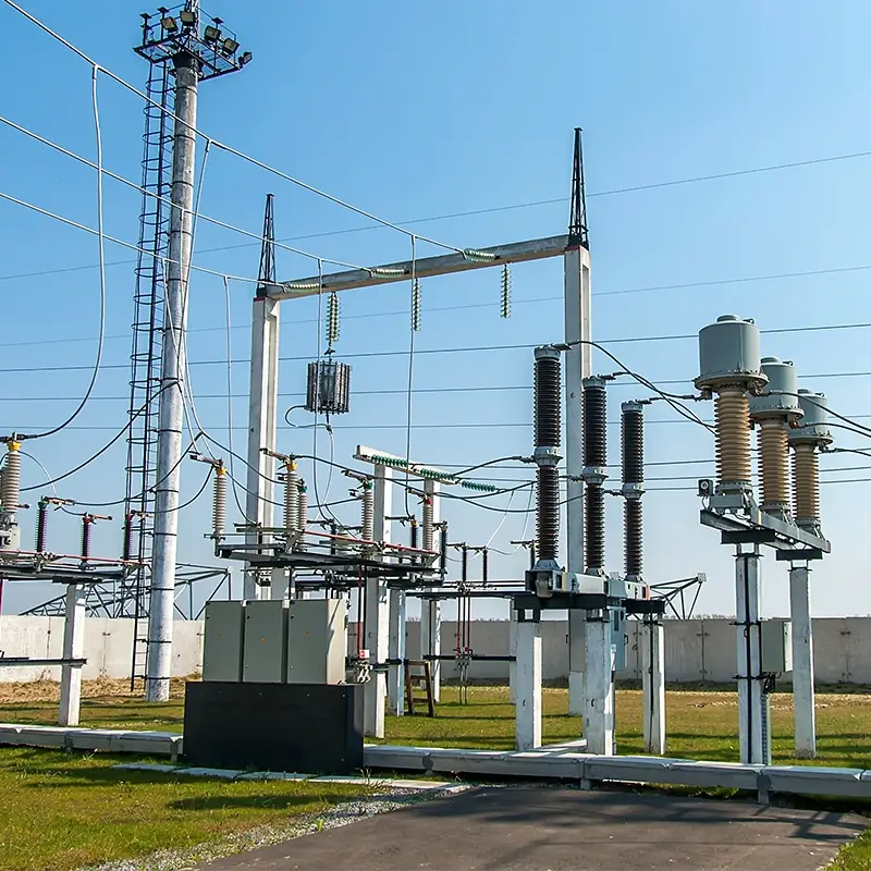
20 basic knowledge about transformers, one article will give you a complete understanding of transformers
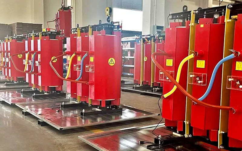
Transformer is a kind of static electrical equipment used to transform AC voltage and current and transmit AC power. It realizes the transmission of electric energy based on the principle of electromagnetic induction. Transformers can be divided into Power Transformers, test transformers, instrument transformers and transformers for special purposes according to their uses: power transformers are necessary equipment for power transmission and distribution, and power distribution to power users; test transformers are equipment for withstand voltage (boost) tests on electrical equipment; instrument transformers are used for electrical measurement and relay protection of distribution systems (PT, CT); transformers for special purposes include smelting furnace transformers, welding transformers, electrolysis rectifier transformers, small voltage regulating transformers, etc.
Power transformer is a static electrical equipment, which is used to convert a certain value of AC voltage (current) into another or several different values of voltage (current) with the same frequency. When AC is passed through the primary winding, an alternating magnetic flux is generated. The alternating magnetic flux induces AC electromotive force in the secondary winding through the magnetic conduction of the iron core. The level of the secondary induced electromotive force is related to the number of turns of the primary and secondary windings, that is, the voltage is proportional to the number of turns. The main function is to transmit electric energy, so the rated capacity is its main parameter.
Rated capacity is a conventional value that represents power. It is a representation of the size of the transmitted electric energy, expressed in kVA or MVA. When the rated voltage is applied to the transformer, the rated current that does not exceed the temperature rise limit under specified conditions is determined based on it. The more energy-saving power transformer is the amorphous alloy core distribution transformer, whose biggest advantage is that the no-load loss value is extremely low. Whether the no-load loss value can be ensured in the end is the core issue to be considered in the entire design process. When arranging the product structure, in addition to considering that the amorphous alloy core itself is not affected by external forces, the characteristic parameters of the amorphous alloy must be accurately and reasonably selected during calculation. Power transformers are one of the main equipment in power plants and substations. The role of the transformer is multifaceted. It can not only increase the voltage to send electric energy to the power consumption area, but also reduce the voltage to various levels of use voltage to meet the needs of electricity consumption. In short, both step-up and step-down must be completed by the transformer. In the process of transmitting electric energy in the power system, voltage and power losses will inevitably occur. When transmitting the same power, the voltage loss is inversely proportional to the voltage, and the power loss is inversely proportional to the square of the voltage. Using a transformer to increase the voltage reduces the power transmission loss.
The transformer is composed of two or more coil windings wound on the same iron core. The windings are connected by an alternating magnetic field and work according to the principle of electromagnetic induction. The installation location of the transformer should be convenient for operation, maintenance and transportation, and a safe and reliable place should be selected. When using a transformer, the rated capacity of the transformer must be selected reasonably. When the transformer is running at no load, a large reactive power is required. These reactive powers should be supplied by the power supply system. If the capacity of the transformer is too large, it will not only increase the initial investment, but also cause the transformer to be in no-load or light-load operation for a long time, increase the proportion of no-load loss, reduce the power factor, and increase the network loss. Such operation is neither economical nor reasonable. If the transformer capacity is too small, the transformer will be overloaded for a long time and easily damage the equipment. Therefore, the rated capacity of the transformer should be selected according to the needs of the power load, and should not be too large or too small.
Classification of transformers
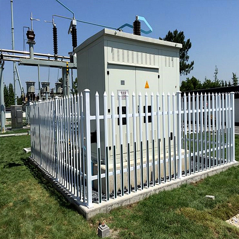
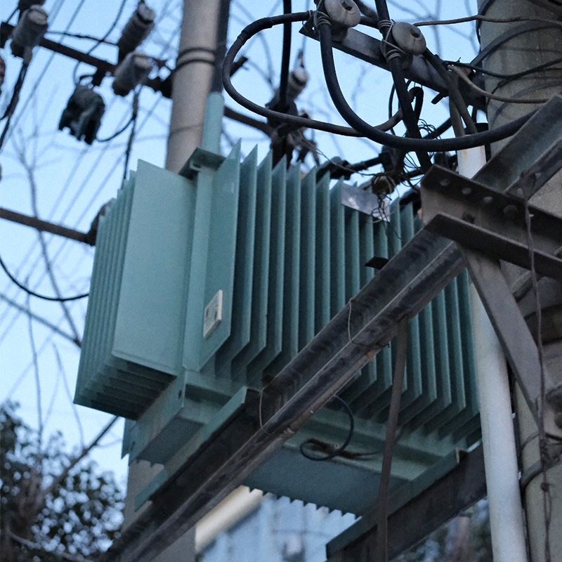
Transformers are divided into: distribution transformers, power transformers, fully sealed transformers, combined transformers, dry transformers, oil-immersed transformers, single-phase transformers, electric furnace transformers, rectifier transformers, reactors, anti-interference transformers, lightning protection transformers, box-type transformer test transformers, corner transformers, high-current transformers, excitation transformers, etc.
Composition of transformers
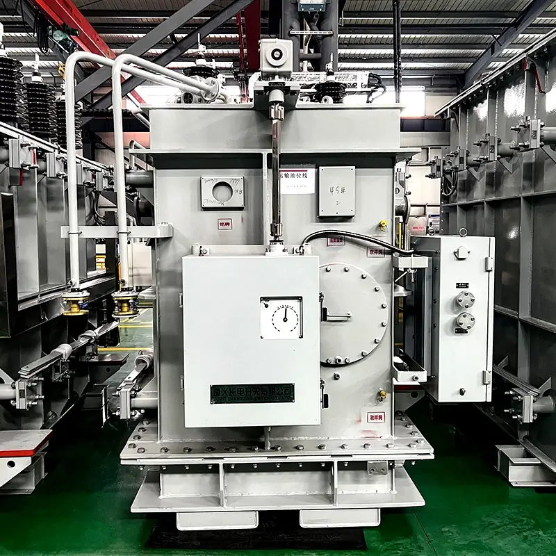
Transformer components are mainly composed of iron cores and coils. In addition, there are oil tanks, oil pillows, insulating bushings and tapping heads.
Main functions of transformers
Transformers can not only increase voltage to send electricity to power consumption areas, but also reduce voltage to various levels of use voltage to meet power consumption needs. In short, both voltage increase and voltage reduction must be completed by transformers.
Function of transformer oil pillows
When the volume of transformer oil expands or shrinks with the change of oil temperature, the oil pillow plays the role of oil storage and oil replenishment, which can ensure that the oil tank is full of oil. At the same time, due to the installation of oil pillows, the contact surface between the transformer and the air is reduced, which slows down the deterioration of the oil. There is also an oil level gauge on the side of the oil pillow to monitor the changes in the oil level. There are three main forms: corrugated type, capsule type, and diaphragm type.
Working principle of transformer oil purifier
Due to the temperature difference between the upper and lower oil temperatures of the operating transformer, the oil circulates in the oil purifier. Harmful substances in the oil, such as water, free carbon, oxides, etc., are absorbed by the silica gel in the oil purifier as the oil circulates, purifying the oil and maintaining good electrical and chemical properties, playing a role in regenerating the transformer oil.
How does the transformer convert voltage?
From the working principle of the transformer, it can be seen that the current enters from the primary winding and flows out from the secondary winding. The direction of the input alternating current changes continuously, which will generate a magnetic field that changes synchronously with the current. The size and direction of the magnetic field change continuously, thereby inducing current in the secondary coil. The voltage on each coil is equal. The more turns of the secondary coil, the higher the voltage output from the secondary coil.
If the number of turns of the primary coil is more than that of the secondary coil, the voltage on the secondary coil will decrease, which is a step-down transformer; conversely, if the number of turns of the primary coil is less than that of the secondary coil, the voltage on the secondary coil will increase, which is a step-up transformer.
Autotransformer
The autotransformer has only one set of coils, and the secondary coil is tapped from the primary coil. In addition to electromagnetic induction transmission, its power transmission also has electrical transmission. This type of transformer has fewer silicon steel sheets and copper wires than ordinary transformers and is often used to adjust voltage.
Transformer voltage change rate
The voltage change rate of the voltage regulator is one of the main performance indicators of the transformer. When the transformer supplies power to the load, the voltage at the load end of the transformer will inevitably drop. The voltage drop value is compared with the rated voltage value, and the percentage is the voltage change rate. It can be expressed by the formula: voltage change rate = [(secondary rated voltage-load end voltage)/secondary rated voltage] × 100%. For ordinary power transformers, when the rated load is connected, the voltage change rate is 4-6%.
Transformer overload operation
When the transformer is operating normally, the load rate of the daily load curve is mostly less than 1.
According to the principle of equivalent aging, as long as the extra life lost during overload and the less life lost during underload can compensate each other, the specified service life can still be obtained. The normal overload capacity of the transformer is formulated on the principle of not sacrificing normal life.
During the entire time interval, as long as the transformer insulation aging rate is less than or equal to 1, and the following conditions are met:
1. During the overload period, the temperature of the hottest point of the winding shall not exceed 140℃, and the upper oil temperature shall not exceed 95℃;
2. The maximum overload of the transformer shall not exceed 50% of the rated load;
Rated voltage of the transformer
Voltage that is too high or too low will affect the normal operation and service life of the transformer, so voltage regulation is required.
Application scope of small transformers
Small transformers refer to single-phase transformers with a capacity of less than 1 kVA, mostly used as power transformers for electrical equipment control, power transformers for electronic equipment, and power transformers for safety lighting.
Consumption in transformer operation
1. Iron loss caused by the core. When the coil is energized, the magnetic lines of force are alternating, causing eddy current and hysteresis losses in the core.
2. Copper loss caused by the resistance of the coil itself. When current passes through the primary and secondary coils of the transformer, the power loss is generated.
How to choose a transformer
1. Clarify the purpose. Is it used to step up or down the voltage?
2. Clarify the number of power phases. Single-phase or three-phase?
3. Clarify the use and environment. Choose the cooling method of the transformer;
4. Determine the material of the coil (copper wire/aluminum wire) according to the actual use and budget;
5. Choose according to the rated parameters of the transformer. These include rated voltage, rated current, and rated capacity.
Transformer core grounding
When the power transformer is operating normally, the core must be reliably grounded at one point. If it is not grounded, the floating voltage of the core to the ground will cause intermittent breakdown discharge of the core to the ground. After the core is grounded at one point, the possibility of forming a floating potential of the core is eliminated.
However, when the core is grounded at more than two points, the uneven potential between the cores will form a loop between the grounding points, and cause the core to be grounded at multiple points and heat up. The core grounding fault of the transformer will cause local overheating of the core. In severe cases, the local temperature rise of the core will increase, light gas will be activated, and even heavy gas will be activated and tripped.
The difference between the neutral point, zero point and zero line
The common connection point where the head (or tail) of the three-phase winding is connected together is called the neutral point of the power supply. When the neutral point of the power supply is well connected to the grounding device, the neutral point is called the zero point; and the wire led from the zero point is called the zero line.
The difference between the energy meter and the power meter
The energy meter can simultaneously indicate active and reactive power and count and power factor, load curve, maximum and minimum load time, etc.; the power meter can only indicate active or reactive value alone.
The harm of casing cracks
Cracks in the casing will reduce the insulation strength and cause further damage to the insulation until it is completely broken down. The water in the cracks may also cause the casing to burst when it freezes.
Function of the central signal device
The central signal device includes accident signals and warning signals, which are installed on the central signal panel in the main control room of the substation. When the circuit breaker of any distribution device in the substation trips due to an accident, the accident signal is activated; when an abnormal operation or operating power failure occurs, the warning signal is activated. Both the accident signal and the warning signal have two signal devices, audio and light. The audio signal can arouse the attention of the on-duty personnel, and the light signal helps the on-duty personnel to determine the nature and location of the fault.
Internal overvoltage
The internal overvoltage is a transition process from one stable state to another stable state caused by a sudden change in the state of the system due to operation, accident or other reasons. In this process, there may be dangerous overvoltages to the system.
The role of high-voltage circuit breakers
1. Control role. When there is no-load current in the circuit, or the current load is relatively large, it can be cut off or closed in time, so as to control the entire line.
2. Protection role. When a circuit fails, such as a short circuit or a circuit breaker, it can have a current interruption ability through the high-voltage circuit breaker. With this protection function, it can prevent the problem of the triggering circuit.
